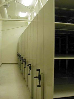
Mobile Shelving System Specifications with Reccessed Rail
AURORA MOBILE
HIGH DENSITY STORAGE SYSTEM SPECIFICATIONS
PART 1 GENERAL
1.1 SCOPE
Furnish labor, material, equipment, special tools, supervision, and services required to complete Aurora Low Profile Mobile System and the attendant shelving systems specified herein and shown on the drawings.
Terms included herein are defined as follows:
Manufacturer: Company manufacturing the product described
Vendor: The dealer, or company selling the product described
Owner: The end user, or customer buying the product described
1.2 RESPONSIBILITY
It shall be the responsibility of each bidder to become fully informed as to the nature and extent of the work required and its relation to any other work in the building.
1.3 RELATED WORK BY OTHERS
Finished floor material shall be in accordance with the room finish schedule and/or specifications.
1.4 QUALIFICATIONS
The mobile system shall be furnished and installed only by those firms engaged in the manufacture of this type of equipment for the last ten years. The entire system shall be warranted by the Manufacturer against defective parts and/or workmanship for a period of five years from the date of final acceptance. The system shall be manufactured in the United States and must be available on Federal Supply Schedule.
1.5 SUBMITTALS
Furnish shop, floor plan and erection drawings, Manufacturer?s written installation instructions, and color samples for color selection by the architect, designer, and/or specifier. Sample of track and the way it joins together must be supplied with bid. Sample of shelving must be supplied with bid.
1.6 EXECUTION
A. Units to be installed with factory trained supervision in accordance with Manufacturer?s written instructions. Certificates of Insallation schoool must be supplied with bid. All rails to be lazer leveled. All rails to be anchored to floor with Hilti Screws.
B. Leave installation in broom-clean condition, with system completely installed and ready for use by Owner.
C. Provide one training session for Owner?s maintenance and operating personnel if requested by Owner at a time of substantial completion. Drawings are representative and may not be exact.
1.6 Execution (continued)
D. Vendor is responsible to verify all measurements and conform to all building and safety codes.
PART 2 - PRODUCTS
2.1 CONFIGURATION
The mobile storage system shall be an integrated assembly of independent, mobile and stationary ranges. Each range shall consist of rigidly attached sections of shelving. All ranges shall have suitable end panels, intermediate panels, back panels, etc., all as specified. The system shall be lazer leveled
2.2 REQUIREMENTS
A. The entire system including carriages, the shelving, and the rails shall be manufactured by a firm regularly engaged in the manufacturing of both steel shelving and high-density mobile storage systems for the past ten years.
B. The Vendor shall be responsible for taking and verifying all dimensions for design and installation. The Vendor shall also verify the capacity of existing storage needs and calculate the future requirements for growth.
2.3 MATERIALS
A. RAIL
1. Rail shall be designed to be anchored to sound flooring and allow for leveling adjustment for uneven floor.
2. Rail shall be located and positioned in accordance with shop drawings Each rail shall have a minimum width of 2.375" and all rails must extend completely under all stationary ranges.
3. Rail shall be level and shall not exceed .0625" maximum variation from true level within any module and .0625" maximum variation between adjacent rails perpendicular to rail direction. The guide rail shall be a minimum of 0.8" in height and the running rail shall be a minimum of 0.5? in height, and be constructed of solid steel. Each section of rail shall be a minimum of 118" with shorter length used only to terminate each individual rail assembly. In addition, each end of the rail shall be connected by means of twin stainless steel dowels pinned between the rail splice to insure vertical and horizontal continuity and gradually transfer the concentrated wheel load to and from adjoining rail sections. This shall be demonstated with the sample required with the bid. The splice shall be designed for the most severe operating conditions. .
2.3 MATERIALS (continued)
B. FLOOR COVERING
Floor covering shall be provided and installed by others.
C. RECESSED RAIL
Construction drawings of recessed rail must accompany the bid. Drawing must show all dimensions and necessary information for the contractor to pour the slab for recessed rail.
D. CARRIAGES
1. Carriages shall be a low profile design with a 3.94? maximum frame height. All carriages shall be welded steel construction. Carriage length and number of rails shall determine carriage load capacity. See addendum for specific requirement. Load shall not cause distortion in any manner.
2. Fixed carriages shall be of the same construction and height as the mobile carriages and anchored to the continuous rails located beneath the fixed carriages for a completely homogeneous system.
3. Carriage splices shall be bolted types designed to maintain proper unit alignment. Carriages shall be straight and square. There shall be no slippage, drag or windup in any splice or welded joint. Fasteners connecting any carriage splice joint shall be vibration-proof in design.
4. Carriage construction shall be such to allow shelving to be securely anchored to each carriage with vibration proof fasteners. Recessed carriages are unacceptable, so as not to cause binding of shelving.
5. Bumpers shall be mounted to the carriage face to help protect material which may extend beyond the shelf face and provide cushioned stop for all carriages without damage or displacement of either material stored or the carriages themselves.
E. Standard carriage lengths shall be from 3? to 24?, and manufactured to exact specifications for depth and length.
F. WHEELS
1. Each carriage shall have two wheels minimum per rail, each wheel being the same size. Dynamic load rating on wheel bearings shall be a minimum of 3300 lb. per wheel.
2. Wheels shall be a minimum of 3.6? effective diameter, precision machined and constructed of cast iron for smooth operation and providing the appropriate load rating for each carriage. Two guide wheels are required for each guide rail. A minimum of two guide rails are required per carriage, a minimum of four guide wheels shall be incorporated into each carriage.
3. Cast iron wheels shall be used due to their high damping capacity, inherent graphite lubricity and exceptional compressive strength.
F. GUIDANCE SYSTEM
1. Provide gapless wheel guidance system through the use of barrier free matching convex rail and concave guide wheel assemblies. Due to housekeeping and safety concerns, rails with gaps on the sides or grooves in the center are not acceptable.
2. Drive shaft shall be solid steel and a minimum of 0.75". Drive shaft shall be a non-load-bearing member of the drive train for ease of locomotion and service.
2.3 MATERIALS (continued)
3. Drive shaft system shall transmit power near the center of the carriage for even distribution of power throughout the carriage. Drive systems that apply power at one end and accumulate ?wind-up? along the length of the base are not acceptable.
4. Drive system must drive all wheels on one side of carriage.
G. DRIVE HOUSING
1. Drive mechanism shall be completely covered by a steel shell which shall allow for placement of the handle.
2. Optional end panels shall be available, and shall be full-height high-pressure laminate, painted steel, European design or Wood-Tek?. Panels shall be full height and width with finished face and sides. Panels shall be constructed and mounted by Manufacturer?s standard method to prevent ?oil canning? and attached with concealed fasteners. End panels shall be available in a variety of colors, laminate options or wood finishes to match or complement shelving color selection.
H. SYSTEM OPERATION REQUIREMENTS
1. Safety Requirements
a. Safety requirements include protection for operator and protection for documents and media.
b. Entire system shall be designed to eliminate any possibility for damage to be caused to any of the properly stored media or documents by closure of any aisle. Width of carriages shall be inclusive of each individual sized media.
2. . Operation
a. Gearing requirements - Reduction drive units must be available at the following ratios:
Effort Ratio Travel per Revolution
1 lb. 1:2000 6.2?
1 lb. 1:4000 4.7?
1 lb. 1:6000 3.6?
1 lb. 1:9000 2.7?
1 lb. 1:11000 2.1?
b. Operator handles shall be available in a three-spoke design, with a push-pull button to fix the carriages in place. Key locks shall also be available to provide a secure system.
c. Operation shall be available at each end of each possible aisle as an option. Operator handles and aisle access both into and around the system shall conform to all applicable codes including, but not limited to, the Americans with Disabilities Act.
I. POWDER COAT PAINT
1. All exposed surfaces shall be painted with Gloss-Tek? Powder Coat Paint, with textured finish, to eliminate fingerprints and provide non-glare environment.
2. Paint finish must be 100% non-emissive, and contain no formaldehyde, methanol, or other solvents.
2.3 MATERIALS (cont)
3. Paint finish must be completely artifact, specimen, and document friendly.
4. Customer to choose from 26 standard colors:
26 Standard Colors
Summit Parchment Adobe Off White
Pebble Tan Mushroom Sand Pebble Gray
Obsidian Gray Sky Gray Mist Pewter
Chisel Black Heritage Blue Desert Sand
Heather Stone Navy Birch Copra
Rebel Shasta Moondust
Baja Blue Flint Quicksilver
PART 3 ? INSTALLATION AND PERFORMANCE REQUIREMENTS
3.1 INSTALLATION
A. Fully grout rails.
B. Permanently attach shelving units to carriages. Stabilize shelving units to comply with mobile storage unit per Manufacturer?s written requirements. Reinforce shelving units to withstand the stress of movement where required and specified.
C. Coordinate installation of rail with general contractor. Install carriages, shelving, and accessories after finishing operations, including painting and floor covering, have been completed. Install system to comply with final layout drawings, in strict compliance with Manufacturer?s printed instructions. Position units level and plumb at proper location relative to adjoining units and related work.
D. Field Quality Control: Remove and replace components which are received scratched, or otherwise damaged, and which do not match adjoining work.
E. Adjust: Adjust components and accessories to provide smoothly operating, visually acceptable installation.
F. Cleaning: Immediately upon completion of installation, clean components and surfaces. Remove surplus materials, rubbish and debris resulting from installation upon completion of work and leave areas of installation in neat, clean condition.
G. Protection: Protect system against damage during remainder of construction period. Advise Owner of additional protection needed to ensure that system shall be without damage or deterioration at time of substantial completion.
3.2 PERFORMANCE REQUIREMENTS
A. No drifting or rolling of stopped carriages shall be acceptable.
B. Play or looseness between drive wheels and wheel axle is not permitted.
C. Bumpers to be 1? thick and to be located in each aisle.
3.3 WARRANTY/SERVICE
Limited Lifetime Warranty
The structural frame of the system shall be covered by the Manufacturer against defective parts and/or workmanship for a lifetime warranty from the date of final acceptance in writing by the customer. For purposes of this warranty, structural frames shall be deemed to exclude all moving parts, controls and guides that have immediate contact with moving parts. During the warranty period, all parts will be provided at no cost. Labor is included at no cost during the first year of the warranty period.
10-Year Limited Warranty: Aurora also warrants that all carriage driven motors and all accessories shall be free from defects in materials and workmanship other than normal wear and tear for a period of ten (10) years from the date of the customer?s written acceptance of installation. During the 10-year warranty period, all parts will be provided at no cost. Labor is included at no cost during the first year of the 10-year warranty period.
3.4 ADDITIONAL REQUIREMENTS
Carriages and shelving shall be from same Manufacturer and supplier. Approved and accepted product and Manufacturer:
Aurora Mobile? High Density Storage System
Aurora Quik-Lok? Shelving
Richards-Wilcox, Inc. c/o NWS
2180 South Constitution
Salt Lake City, Utah 84119
Phone: 866-328-5066
FAX: 801-886-2530
|